[ This article is reposted with permission of Luca Ingianni. Luca specializes in bringing DevOps to the embedded world: improving both the lives of engineers and the quality of their products. While not specific to Unit Testing, it discusses a tool which might be useful to members of the ThrowTheSwitch.org community ]
I’m very excited to transfer the principles of DevOps to embedded software and the Internet of Things (gotta be buzzword-compliant), and new tools promise to get us closer to this goal.
A lot is happening in the embedded system tooling space right now; I’m hopeful that the methods used in embedded may finally catch up to the rest of software development.
A lot of startups explore new ways to aid in development, and make the difficult world of embedded development more welcoming.
Introducing Jumper Virtual Lab
Today, I want to introduce you to one such new, interesting tool: Jumper Virtual Lab As you read my discussion of it, keep in mind that Jumper Virtual Lab is still in beta, and various rough edges will certainly be smoothed out as the product is released.
This post will be the first in a small series, exploring Virtual Lab. As is custom in the embedded world, our first attempt will be to get a LED to blink.
Except, with a twist: first we’ll use a physical µC, and after that we’ll execute the exact same binary on Virtual Lab’s simulation, to find out if it actually works like the real thing.
What is it?
Virtual Lab is a hardware virtualisation solution for embedded systems. It allows to simulate microcontrollers to a degree that native code will run on these virtual devices.
This opens a range of possibilities:
- Create virtual prototypes, and try your software under real-life conditions before physical prototypes have even been delivered
- Create test scenarios which are otherwise hard to achieve: write to read-only memory, mess with data lines, pause and resume execution of an entire assembly (sensors and µC) without fearing desynchronisation, etc
- Be unconstrained by number of prototypes: run multiple tests in parallel, afford all developers heaps of virtual devices to try things with
- Execute at more than real-life speed, or skip in time, to accelerate tests
- Simplify your CI/CD pipeline, by not having to rely on temperamental HiLs: turn system test into an all-software affair
Getting to Blinky
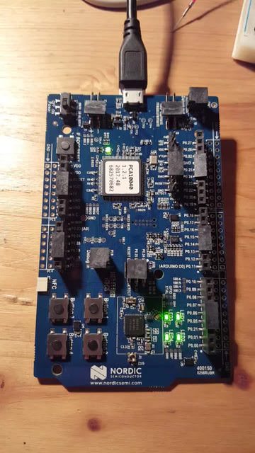
As promised, we’ll start by using real, proper hardware: the Nordic Semiconductors nRF52 ARM-based microcontroller.
We’ll use Nordic’s nRF52 DK development kit and the SDK’s blinky code example as the basis for our physical tests. Once we get our toolchain running, we’ll satisfy ourselves that Jumper can successfully run the same binaries in its simulation.
Creating the Blinky Binary
Just to make sure you understand my starting point, here’s an outline of the environment I used:
- nRF5x SDK 14.2.0
- GNU Am Embedded Toolchain 7-2017-q4-major
- nRF52 DK development board
- Jumper 0.0.52
Go to the SDK’s blinky example, build it, and flash it:
$ cd nRF5_SDK_14.2.0_17b948a/examples/peripheral/blinky/pca10040/blank/armgcc/

$ make
mkdir _build
cd _build && mkdir nrf52832_xxaa
Assembling file: gcc_startup_nrf52.S
Compiling file: system_nrf52.c
Compiling file: main.c
Compiling file: boards.c
Compiling file: app_error.c
Compiling file: app_error_weak.c
Compiling file: app_util_platform.c
Compiling file: nrf_assert.c
Compiling file: nrf_strerror.c
Linking target: _build/nrf52832_xxaa.out
   text    data     bss     dec     hex filename
   2088     108      28    2224     8b0 _build/nrf52832_xxaa.out
Preparing: _build/nrf52832_xxaa.hex
Preparing: _build/nrf52832_xxaa.bin
DONE nrf52832_xxaa

$ sudo nrfjprog --family nRF52 -e
Erasing user available code and UICR flash areas.
Applying system reset.

$ sudo ~/projects/spikes/nrf52/nrfjprog/nrfjprog --family nRF52 --program _build/nrf52832_xxaa.hex
Parsing hex file.
Reading flash area to program to guarantee it is erased.
Checking that the area to write is not protected.
Programing device.

$ sudo ~/projects/spikes/nrf52/nrfjprog/nrfjprog --family nRF52 -r
Applying system reset.
Run.
And see its glory:
installing Jumper Virtual Lab
Conveniently, Jumper comes as a Python 2 module and can be installed via pip.
Follow the instructions here
Once it’s installed, let’s try it out:
$ jumper run --bin _build/nrf52832_xxaa.bin
Loading virtual device
.........^C%
Success! I guess.
Getting to Virtual Blinky
I mean, the previous command was clearly doing… something.
But it’s not a proper blinky yet, is it? I don’t know about you, but I didn’t see anything blinking at all.
Let’s change that!
Let’s build a simple blinky-simulation:
#!/usr/bin/python2

from jumper.vlab import Vlab

# this array holds the four LEDs' visualisation
LEDs=["..","..","..",".."]

def on_pin(number, level):
    """This function will be called back for each state change of a pin.
    In this case, we use it to simulate the visible behaviour of the nRF52 DK:
    the blinky example makes the DK's four LEDs bink.
    This function visualise these four leds"""

    # update the state of the simulated LEDs
    if level:
        LEDs[number-17] = "XX"
    else:
        LEDs[number-17] = ".."

    # show them in the terminal
    print("   " + LEDs[0] + "   " + LEDs[1])
    print("   " + LEDs[2] + "   " + LEDs[3])

    # go back up three lines, so we overwrite our previous rendering of the LEDs the next time around
    print("\033[3A")

# set up the device simulation
dir="."
fw_bin="_build/nrf52832_xxaa.bin"
v = Vlab(working_directory=dir)
v.load(fw_bin)

# register the callback which visualises the LEDs
v.on_pin_level_event(on_pin)

# run the simulation
v.start()
Once created, you can run it:
$python test.py
You'll see happy blinking XX's. Isn’t it pretty?
Verdict: so far, so cool
So there you have it: a simple device simulation in (generously) ten lines of code, which can be plugged right in place of a physical device.
Compared to where we were only a decade ago (and where most embedded development teams still are), this is pretty amazing.
The next installment of this post series will use Jumper for proper testing, and eventually place it in a complete CI workflow. I’m excited to see how well it’ll work. Are you?


